Coupled Atomistic Continuum Modeling and Simulation
Faculty Participants
Catalin Picu
Professor
M. S. Shephard
Professor, Scientific Computation Research Center
Current and Former Students
Nithin Mathew
Dybiendu Datta
Mohan Nuggehaly
Ben Franzdale
Introduction
Most physical problems of interest are of a multiscale nature. The behavior observed at the system scale depends on phenomena taking place on multiple spatial and temporal scales. For example, deformation of metals which is usually described at the macroscale by continuum plasticity, is governed by the deformation of individual grains, which is controlled by the nucleation, multiplication and interaction of dislocations.
Modeling such phenomena is notoriously difficult due to the large range of spatial and temporal scales involved. There are two broad classes of multiscale methods: sequential and concurrent. In sequential methods, a physical process is modeled on given scale and the net, averaged behavior is sought. This response is input into another model that describes the physics on the immediately superior scale. Obviously, this approach is applicable when “relevant scales” can be clearly identified. The other alternative is to use multiple models concurrently, i.e. to divide the problem domain in sub-domains over which different models are used.
The technologies developed in this program are of the concurrent type and are focused on coupling discrete (atomistic) and continuum models. This coupling is challenging due to the fundamental differences between the two types of models. Discrete models are non-local and their potential function is non-convex. Continuum models are governed by a convex potential, and may be linear or non-linear, local or non-local. The advantage of the discrete models is that they allow “damage” to occur naturally due to the non-convex nature of the potential. Continuum models cannot account for such effects (e.g. crack nucleation and propagation, dislocation nucleation etc). In the continuum, defects have to be included by the modeler.
In this project we develop a coupled atomistic-continuum method applicable at zero Kelvin (AtC) as well as at finite temperatures (AtCT). The main idea is to use atomistic analysis only at places where needed (large strain gradients) and continuum analysis elsewhere, for efficiency.
Results
Athermal Model (Coupled Molecular Statics-Continuum)
The method is based on the adaptive selection of models from a model hierarchy. Three models are currently used: an atomistic model (molecular statics), a linear elastic and a non-linear elastic continua. The atomistic model is the most accurate in the hierarchy and is used as reference. The constitutive behavior of the two continua is calibrated based on the atomistic model.
The models are selected form the set based on error indicators developed for this purpose. The error indicator used to identify the transition from non-local continuum to atomistics is developed starting from a recently proposed criterion for dislocation nucleation developed by Miller and Acharya. The error indicator used to discriminate between the linear and the non-linear continua is based on comparing strain energies predicted using the two models.
At any given time, the error indicators are used to partition the problem domain in regions to be represented by the three models. The boundary between the two continuum models requires no special treatment. The boundary between the non-linear elasticity model and the atomistic model needs special attention. At this boundary one defines a buffer region in which the two models are superimposed. The solution is obtained by imposing the force equilibrium everywhere in the problem domain, or, equivalently, by minimizing the residual. In the buffer region the residual is computed as a weighted sum of the atomistic and continuum residuals. In addition, the compatibility of displacements between the two models in the buffer region is imposed in a mean sense (in average, over each continuum element in the buffer).
The method has been extensively verified against fully atomistic models. It was shown that it passes the patch test. It is fully 3D and is implemented in an parallel computing environment.
Few examples are shown below.
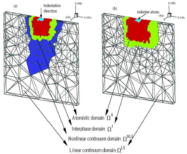
Nanoindentation
Figure 1 shows the simulation of nanoindentation using a square punch. The punch is represented by light blue. The other colors represent sub-domains corresponding to the three models used. The red represents the atomistic region, green is the buffer and dark blue shows the non-linear elastic continuum. The rest of the model is linear elastic. The model on the right uses only two models (atomistic and linear elastic). One can see that the atomistic region is larger in this case.
Cavitation
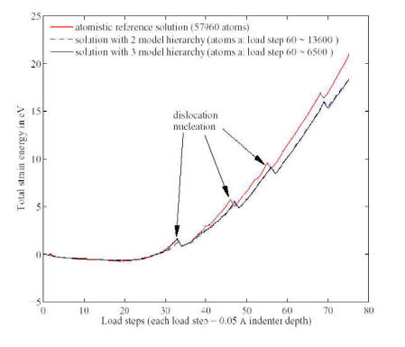
Figure 2 shows the total model strain energy computed with the coupled model (3 member hierarchy) along with the same measure evaluated from a fully atomistic model. The agreement is very good. The drops correspond to the nucleation of dislocations from the edges of the indenter.
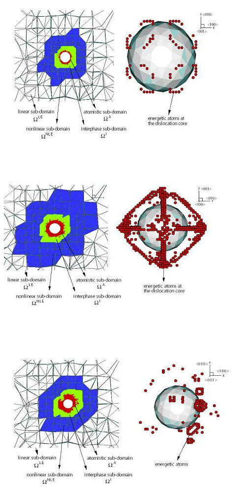
In the next model we represent the evolution of a void in a large block of material (Al) subjected to hydrostatic loading. Dislocations nucleate from the surface of the void and evolve in the surrounding material. Initially, several loops nucleate in a symmetric fashion (due to the underlying symmetry of the crystal) and interact forming a stacking fault tetrahedron around the void. This structure is quite stable against further nucleation of dislocations from the void (which leads to void growth). However, upon applying sufficiently large load, the tetrahedron is destroyed and a more complicated dislocation structure forms. The next few figures show the initial nucleation stage, the stacking fault tetrahedron and the debris left in the model after full unloading. As before, colors represent sub-domains in which various models (as indicated) are adaptively selected.
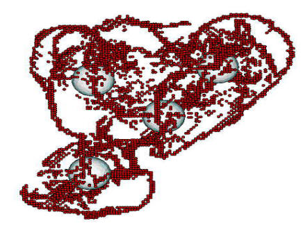
Nanoporous material
A nanoporous material was also considered and subjected to hydrostatic tensile loading. Figure 4 shows the dislocation structure evolving in the neighborhood of 4 voids located relatively close to each other.
Finite Temperature Model (coupled Molecular Dynamics-Continuum)
Coupling discrete and continuum models at finite temperatures is more challenging. While continuum models use different differential equations for conservation of momentum and for transport (mass or heat), these are not decoupled when the discrete view is taken. Particle motion is the only physics in atomistic models. Coupling can be introduced in a semi-heuristic way in continuum models, but this requires additional constitutive relations. This fundamental discrepancy poses serious challenges to any attempt to concurrently couple such models. Furthermore, continuum models use convex potentials and the concept of dissipation to represent plastic deformation. They are usually local, although non-local forms of the constitutive equations can be used. Discrete models have non-convex potentials with multiple local minima and are intrinsically non-local.
In this work we develop a method to couple discrete (atomistic) and continuum models at finite temperatures which, for computational efficiency, uses standard wave and heat equations in the continuum. A specially designed interface region couples the two models. A procedure is devised to separate the total kinetic energy of the discrete model in two parts, which are treated as mechanical and thermal energy in the continuum. Full, bi-directional mechanical and thermal coupling is demonstrated in 1D.
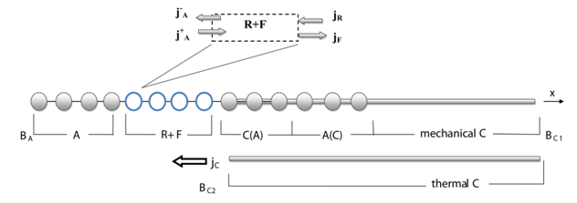
The figure shows a 1D model in which the left side is discrete (A) and the right if continuum (C). The continuum model has a mechanical and a thermal component which are not coupled (energy is not transferred from one component to the other). The interface is composed of the three domains R+F, C(A) and A(C). Domains A(C) and C(A) provide mechanical coupling (long wavelengths) and function similar to the interface of the athermal, zero Kelvin, model. Domain R+F divides the phonon spectrum into long and short wavelength components which are transmitted to the continuum model as mechanical and thermal energy, respectively. It also preserves the thermal equilibrium of A if no external perturbation is applied.
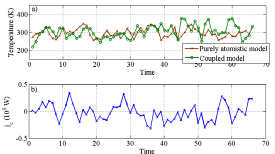
The next figure shows the behavior of the interface (R+F) in thermodynamic equilibrium. The temperature is kept constant in time, while the coupling flux flowing between the thermal component of the continuum and A, \(j_C\), oscillates about zero.
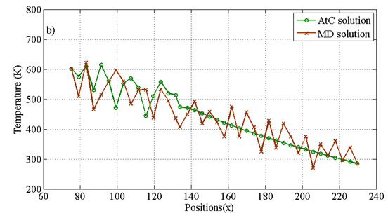
If a temperature differential is applied across the model, the temperature gradient becomes constant, as expected. This is shown in the next figure and demonstrates that the coupled method works properly. The green line shows results obtained from the coupled AtCT, while the brown line represents results obtained with a fully discrete model.
Publications
- [1]N. Mathew, C. R. Picu, and M. Bloomfield, “Concurrent coupling of atomistic and continuum models at finite temperature,” Computer Methods in Applied Mechanics and Engineering, vol. 200, no. 5–8, pp. 765–773, Jan. 2011, doi: 10.1016/j.cma.2010.09.018.
A concurrent multiscale method for coupling discrete (atomistic) and continuum models at finite temperatures is presented. Motion of atoms is governed by an inter-atomic potential and is represented by molecular dynamics. A thermo-mechanical continuum defined by standard differential equations of conservation of momentum and heat transport is used. The coupling is performed by an interface region where the two models overlap. The phonon spectrum of the discrete region is divided into a low frequency part which is transferred to the continuum model as mechanical waves, and a high frequency component which is modeled in the continuum as diffusive heat transport. Seamless mechanical coupling is ensured by imposing weak compatibility of displacements in the interface region. The method is implemented in 1D and full bi-directional thermal and mechanical coupling is demonstrated in thermodynamic equilibrium and in non-equilibrium.
- [2]C. Picu and D. Zhang, “Multiscale Modeling of Solute Bulk Diffusion at Dislocation Cores,” International Journal for Multiscale Computational Engineering, vol. 7, no. 5, pp. 475–485, 2009, doi: 10.1615/IntJMultCompEng.v7.i5.80.
A sequential multiscale modeling methodology is developed to study the diffusion of solute atoms in the vicinity of a dislocation core and the kinetics of the ensuing clustering process. The problem is set up in the continuum sense, taking into account the coupling between diffusion and deformation. Specifically, gradients of both strain and concentration drive diffusion, and the elastic constants are considered functions of the local solute concentration. These coupling parameters are calibrated from atomistic models. The problem is solved using a finite element formulation. Mg clustering at an edge dislocation in Al-5%Mg is studied, which is relevant for static and dynamic strain aging. The model is used to test the validity of the Cottrell-Bilby-Louat expression, broadly used to describe the kinetics of solute clustering at dislocation cores. It is concluded that the formula does not predict the variation in time of the concentration at every point within the cluster, the purpose for which it is customarily used. However, it properly describes the evolution of a global measure of the cluster size.
- [3]J. Fish et al., “Concurrent AtC coupling based on a blend of the continuum stress and the atomistic force,” Computer Methods in Applied Mechanics and Engineering, vol. 196, no. 45–48, pp. 4548–4560, Sep. 2007, doi: 10.1016/j.cma.2007.05.020.
A concurrent atomistic to continuum (AtC) coupling method is presented in this paper. The problem domain is decomposed into an atomistic sub-domain where fine scale features need to be resolved, a continuum sub-domain which can adequately describe the macroscale deformation and an overlap interphase sub-domain that has a blended description of the two. The problem is formulated in terms of equilibrium equations with a blending between the continuum stress and the atomistic force in the interphase. Coupling between the continuum and the atomistics is established by imposing constraints between the continuum solution and the atomistic solution over the interphase sub-domain in a weak sense. Specifically, in the examples considered here, the atomistic domain is modeled by the aluminum embedded atom method (EAM) inter-atomic potential developed by Ercolessi and Adams [F. Ercolessi, J.B. Adams, Interatomic potentials from first-principles calculations: the force-matching method, Europhys. Lett. 26 (1994) 583] and the continuum domain is a linear elastic model consistent with the EAM potential. The formulation is subjected to patch tests to demonstrate its ability to represent the constant strain modes and the rigid body modes. Numerical examples are illustrated with comparisons to reference atomistic solution.
- [4]M. A. Nuggehally, M. S. Shephard , Professor, C. R. Picu, and J. Fish, “Adaptive Model Selection Procedure for Concurrent Multiscale Problems,” International Journal for Multiscale Computational Engineering, vol. 5, no. 5, pp. 369–386, 2007, doi: 10.1615/IntJMultCompEng.v5.i5.20.
An adaptive method for the selection of models in a concurrent multiscale approach is presented. Different models from a hierarchy are chosen in different subdomains of the problem domain adaptively in an automated problem simulation. A concurrent atomistic to continuum (AtC) coupling method [27], based on a blend of the continuum stress and the atomistic force, is adopted for the problem formulation. Two error indicators are used for the hierarchy of models consisting of a linear elastic model, a nonlinear elastic model, and an embedded atom method (EAM) based atomistic model. A nonlinear indicator , which is based on the relative error in the energy between the nonlinear model and the linear model, is used to select or deselect the nonlinear model subdomain. An atomistic indicator is a stress-gradient-based criterion to predict dislocation nucleation, which was developed by Miller and Acharya [6]. A material-specific critical value associated with the dislocation nucleation criterion is used in selecting and deselecting the atomistic subdomain during an automated simulation. An adaptive strategy uses limit values of the two indicators to adaptively modify the subdomains of the three different models. Example results are illustrated to demonstrate the adaptive method.
- [5]D. K. Datta, C. R. Picu, and M. S. Shephard, “Composite Grid Atomistic Continuum Method: An Adaptive Approach to Bridge Continuum with Atomistic Analysis,” International Journal for Multiscale Computational Engineering, vol. 2, no. 3, pp. 401–420, 2004, doi: 10.1615/IntJMultCompEng.v2.i3.40.
The Composite Grid Atomistic Continuum Method, a method to couple continuum and atomistic models, is proposed in a three-dimensional setting. In this method, atomistic analysis is used only at places where it is needed in order to capture the intrinsically nonlinear/nonlocal behavior of the material at the atomic scale, while continuum analysis is used elsewhere for efficiency. The atomistic model is defined on a separate grid that overlaps the continuum in selected regions. The atomistic and the smallest scale continuum model are connected by appropriately defined operators. The continuum model provides boundary conditions to the discrete model while the atomistic model returns correcting eigenstrains. The adaptive selection of the spatial regions where the atomistic correction is needed is made based on error indicators developed to capture the nonlinearity and nonlocality modeling errors. The method is applied to represent dislocation nucleation from crack tips and nanoindentation in aluminum.
- [6]C. R. Picu, “Atomistic-continuum simulation of nano-indentation in molybdenum,” Journal of Computer-Aided Materials Design, vol. 7, no. 2, pp. 77–87, May 2000, doi: 10.1023/A:1026527931918.
Simulations of nano-indentation in bcc molybdenum are performed using a coupled atomistic-continuum method and a multi-body interatomic potential which includes angular forces. The indenter is flat and rigid while the indented material is a single crystal having its ⦑100⦒ and ⦑111⦒ directions respectively parallel to the indentation direction, in separate simulations. Indentation is accommodated by elastic deformation of the surface, up to an indenter displacement of about 6 Å, and by nucleation of crystalline defects for deeper indents. When indented in the ⦑100⦒ direction, the crystal twins under the indenter, while indentation in the ⦑111⦒ direction produces dislocation nucleation from the stress concentration sites at the indenter edge. The critical loads for these events are computed and the nucleation mechanism is observed. The results are compared with available experimental data.