Epoxy and Vitrimer Molecular Networks and Composites
Nanocomposites with Enhanced Strength and Toughness
Project Sponsors
Faculty Participants
Current and Former Students
Molecular networks – an Introduction
Dump a bunch of threads in a box, mix them and you’ve got an entangled network which is not easy to take apart or to break. Polymers at normal melt densities are like that. If long enough the molecular strands will entangle and the resulting topological interactions provide strength to the network. If crosslinks are added to link strands that come in contact, a permanent network results, i.e. a thermoset. Rubber and epoxy are examples of thermosets with permanent, covalent crosslinks. Rubber is sparsely crosslinked and above its glass transition in ambient conditions, while epoxy is densely crosslinked and typically in the glassy state when in service.
If crosslinks are not permanent, the material behavior has both solid-like and fluid-like features. In most cases, the crosslinks may break due to applied stress or/and thermal fluctuations and may reform at some other location in the sample. These networks are called dissociative. Vitrimers belong to a special class of networks with transient crosslinks, in which the bonds open only to exchange strands with another bond that happens to be nearby. Therefore, the crosslink density is strictly constant in such networks, while in dissociative networks the crosslink density may decrease or fluctuate during deformation.
Our group explores the mechanics of epoxy and vitrimers both by modeling and experimentally. The main objective of the work on epoxy is to increase its toughness. Epoxy has high stiffness and strength (compared with other polymeric network materials) and therefore is an indispensable structural material. However, it is brittle in the fully cured state and this is non-ideal in design and dangerous in applications. Substantial effort has been dedicated for several decades to toughening epoxies and commercial solutions exist, e.g. based on the incorporation of elastomeric beads. Our research focuses on using structural heterogeneity on multiple scales to intrinsically toughen epoxy.
Vitrimers are a new class of materials, with only one-decade long history. Many aspects of their mechanics are unknown and material optimization for specific applications is in progress. Our work aligns with this broad direction. The major advantage of networks with transient crosslinks is that they behave as thermosets at low temperatures, and as thermoplastics at temperatures at which the crosslinks unbind. Therefore, these thermosets can be recycled, reshaped and may exhibit shape memory. One of the major hopes is that vitrimers will eventually replace the current thermosets which degrade upon increasing temperature and cannot be recycled.
Epoxy – Experimental
Toughening by the addition of nanoparticles
Through an international collaboration involving researches from Austria and Romania, we developed a method to modify the toughness of epoxies after fabrication, in parts of the sample or in the entire sample, at will. This is based on using silica nanoparticle additions with interfaces with epoxy which are responsive to UV irradiation or to increasing the temperature above a limit. The interface is modified using azidophenyl silane, as shown in Fig. 1.
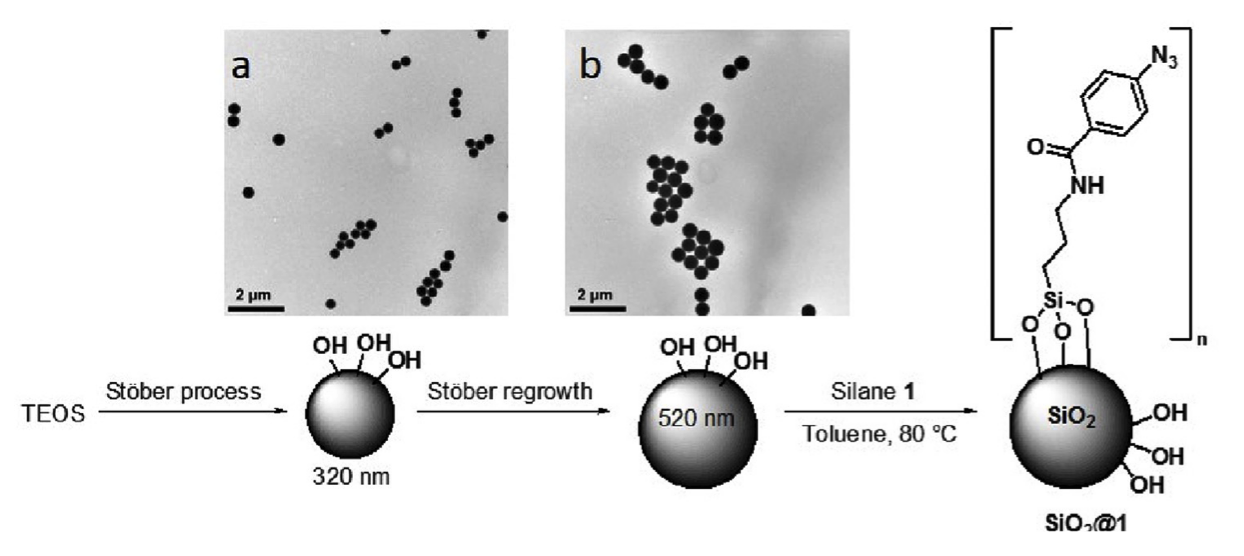
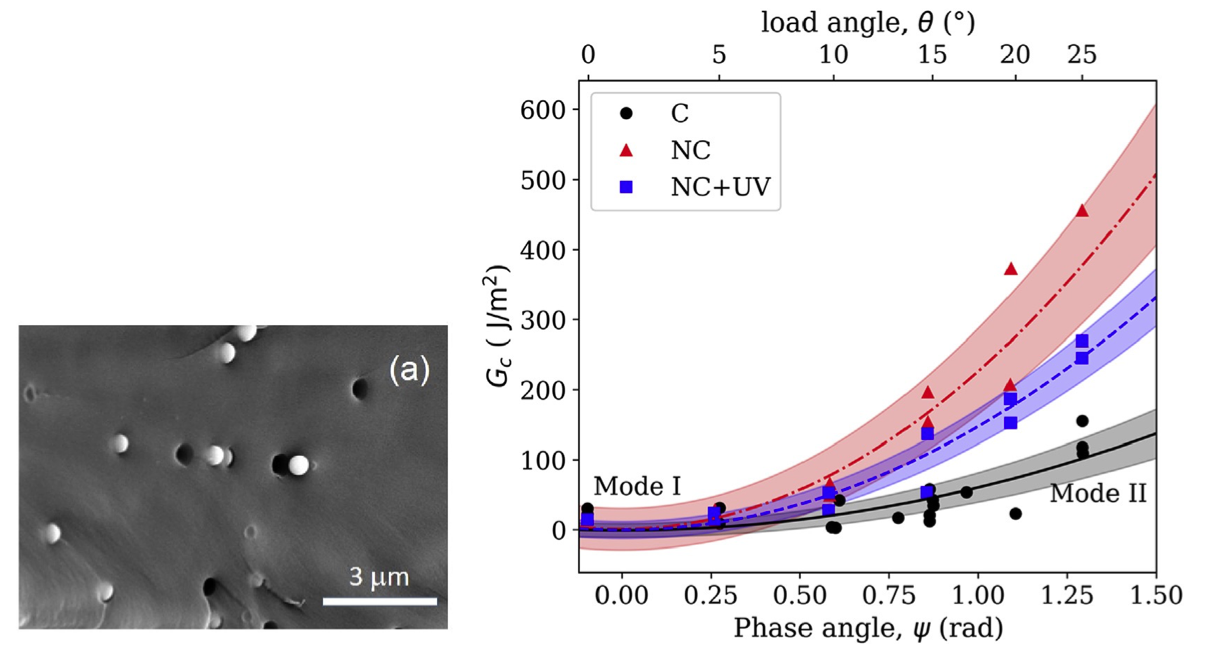
When mixed in epoxy, the interface is weak. Under stress, it opens and allow the nucleation and growth of voids which, in turn, implies energy dissipation and hence toughening. However, if exposed to UV light, the functionalization decomposes promoting a reaction that renders the interface with the surrounding epoxy strong. This prevents cavitation and the material becomes brittle. Figure 2 shows voids growing at sites where nanoparticles are embedded, which demonstrates the mechanism outlined here, the increase of the fracture toughness of the material upon the addition of functionalized nanoparticles and its decrease upon exposure to UV. The method can be used to pattern the local properties of a part by local exposure to UV.
- R.C. Picu, K.K. Krawczyk, Z. Wang, H.P. Moghaddam, M. Sieberer, A. Lassnig, W. Kern, A. Hadar, D.M. Constantinescu, Toughening in nanosilica-reinforced epoxy with tunable filler-matrix interface properties, Comp. Sci. Technol., Vol. 183, pp. 107799, 2019
- M. Kamble, A. Lakhnot, N. Koratkar, R.C. Picu, Heterogeneity-induced mesoscale toughening in polymer nanocomposites, Materialia, Vol. 11, pp. 100673, 2020
Toughening and fatigue life improvement by the addition of carbon nanotubes
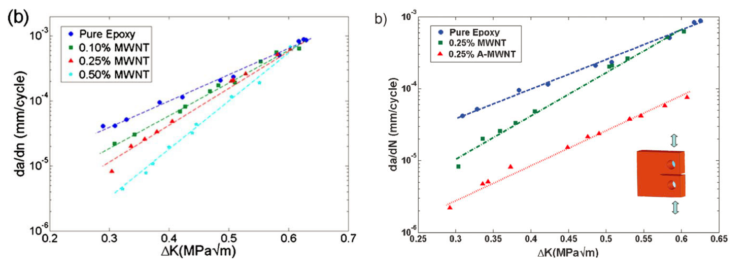
In another branch of this work we studied the effect of carbon nanotubes on fatigue crack growth in epoxy nanocomposites. By dispersing un-functionalized carbon nanotubes in commercial DGEBA epoxy, we observed slowdown of crack growth at small loading amplitudes (stress intensity factor amplitudes). However, the effect was lost at high loading amplitudes. The slowdown was compatible with predictions of the crack bridging model which is based on the idea that fibers (or carbon nanotubes, in this case) that bridge the two faces of the crack, apply a pull-back force which tends to close the crack and shields the crack tip. This effect is shown in Fig. 3 (Left).
While the result is positive, it is only partly satisfying since no enhancement is obtained in the high amplitude range. To address this, we used carbon nanotubes functionalized with amines. In the functionalization process, the tubes also become shorter. The amine groups ensure good bonding to the epoxy matrix. Using these tubes as fillers in epoxy led to a drastic reduction of the crack growth rate, by about 10 times, which persists at large load amplitudes, Fig. 3 (Right). This implies the extension of the fatigue life by at least one order of magnitude.
- W. Zhang, C. R. Picu, and N. Koratkar, “Suppression of fatigue crack growth in carbon nanotube composites,” Applied Physics Letters, vol. 91, no. 19, p. 193109, 2007.
- W. Zhang, I. Srivastava, Y.-F. Zhu, C. R. Picu, and N. A. Koratkar, “Heterogeneity in epoxy nanocomposites initiates crazing: significant improvements in fatigue resistance and toughening,” Small, vol. 5, no. 12, pp. 1403–1407, 2009
Heterogeneous epoxies – nanoscale control via phase separation
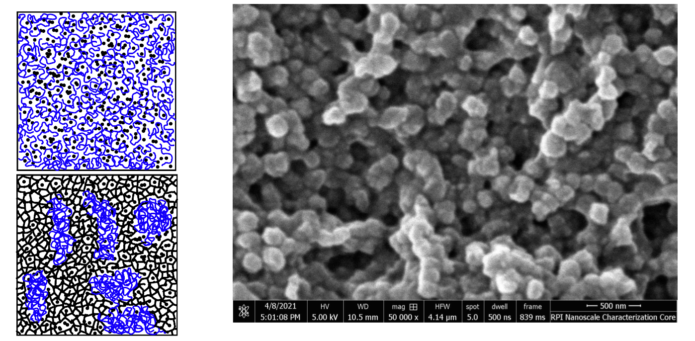
Epoxies are nominally homogeneous. In this project we explore thermosets with controlled degrees of heterogeneity, on scales ranging from 100 nm to mm. Heterogeneity on the nanoscale is controlled via phase separation. This is achieved by working with blends of network forming resin-hardener and thermoplastics. We work with PETA, which is a tetra-functional monomer with 4 acrylates, and 2-EHM, which has one methacrylate group. PETA-2-EHM form a molecular network in the presence of an initiator. Polyethylene glycol (PEG) is added to the solution. In the process of polymerization and network crosslinking, PEG separates and forms sub-domains of size controlled by the rate of crosslinking and by the molecular weight of the PEG molecules. Figure 4 shows a schematic of the phase separation process and an SEM image of the resulting material after the PEG sub-domains have been washed out. The resulting porosity provides insight into the distribution and size of the softer PEG sub-domains.
Modeling
Hierarchical (fractal) microstructure
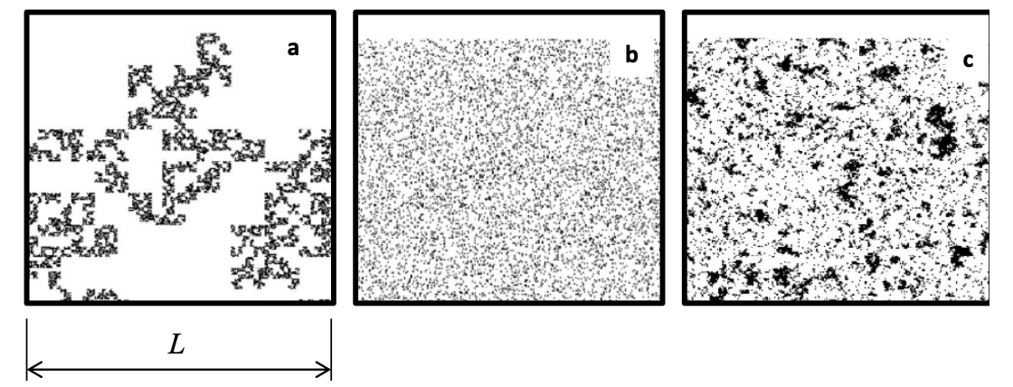
The effect of correlations of the spatial distribution of inclusions in a two-phase composite was studied numerically. Microstructures with fractal distribution of inclusions are compared with random inclusion distributions of same volume fraction. The elastic-plastic response of composites with stiff elastic inclusions and elastic-plastic matrix is studied. Composites with hierarchical multiscale structure with different distributions of inclusions are presented in Figure 5.The figure shows a microstructure in which inclusions form a fractal (a), a microstructure with randomly distributed inclusions (b), and a microstructure in which inclusions are distributed in a spatially correlated way, with the correlation being exponential.
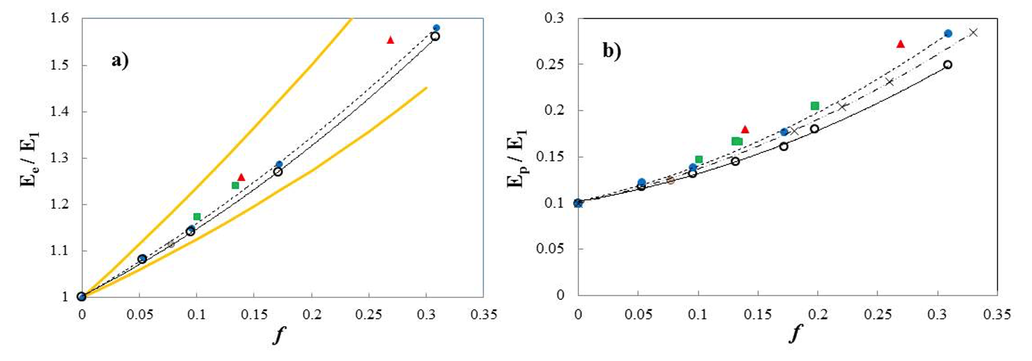
The mechanical behavior of these composites was studied using finite element models. The matrix was modeled with a bilinear model (linear elastic of Young’s modulus E1), and linear hardening beyond the yield stress). Inclusions are considered linear elastic in all cases, with Young’ s modulus 6E1. The composite has also a bilinear response when loaded uniaxially. The slope of the elastic region is denoted by Ee (effective elastic modulus), while the slope of the stress-strain curve after the yield point is denoted by Ep. Figure 6 shows the effective moduli Ee and Ep for various systems. The open symbols show results for the random microstructures. The various filled symbols represent results for fractal microstructures. As the fractal dimension increases, the symbols move farther from the continuous black line which was fitted to the open symbols. The yellow lines represent the Hashin-Shtrikman bounds for the random microstructures. In (b), the crosses represent data for the exponentially correlated microstructures shown in Fig. 5c. The distribution of inclusions has a strong influence on the mechanical response of the composite. As the range of spatial correlations of the distribution increases, the composites are stiffer and strain harden more once in the plastic range.
Other studies concerned with the effect of the (fractal or correlated) material architecture on composite properties are presented in references listed below.
- R.C. Picu, S. Sorohan, M.A. Soare, D.M. Constantinescu, “Towards designing composites with stochastic composition: effect of fluctuations in local material properties,” Mech. Mater., Vol. 97, p. 59-66, 2016
- C. R. Picu, Z. Li, M. A. Soare, S. Sorohan, D. M. Constantinescu, and E. Nutu, “Composites with fractal microstructure: The effect of long range correlations on elastic–plastic and damping behavior,” Mechanics of Materials, vol. 69, no. 1, pp. 251–261, Feb. 2014
- M. A. Soare and C. R. Picu, “Boundary value problems defined on stochastic self-similar multiscale geometries,” International Journal for Numerical Methods in Engineering, vol. 74, no. 4, pp. 668–696, Apr. 2008
- M. A. Soare and C. R. Picu, “An approach to solving mechanics problems for materials with multiscale self-similar microstructure,” International Journal of Solids and Structures, vol. 44, no. 24, pp. 7877–7890, Dec. 2007
Vitrimers
Stress relaxation in vitrimers
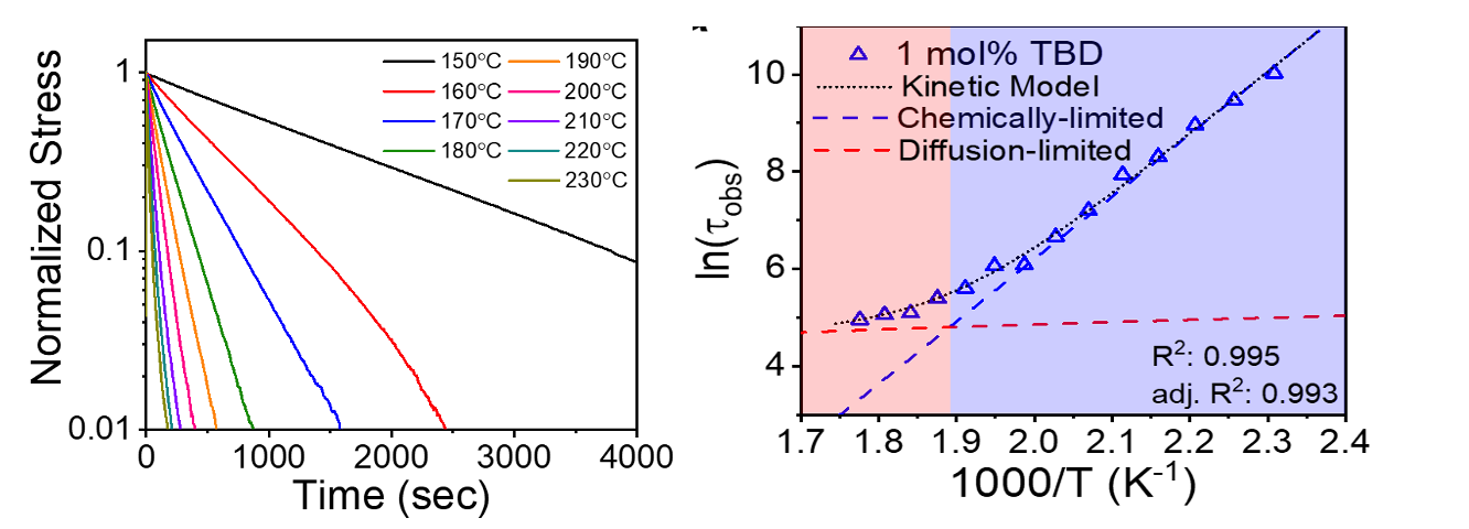
Stress relaxation in vitrimers is controlled by intermolecular friction and the rate at which crosslinks undergo the transesterification reaction. At temperatures above the glass transition temperature, \(T_g\), and below the vitrification temperature, \(T_v\), the material behavior is controlled primarily by the dynamics of the crosslinks. In collaboration with a group from Wright-Patterson Air Force Base Labs, we studied vitrimers formed by DGEBA and sebacic acid crosslinked in the presence of a catalyst. Figure 7 (Left) shows a semilog plot of stress relaxation curves for a given catalyst concentration and at various temperatures. The early time relaxation is exponential, as demonstrated by the straight lines in this representation. Figure 7 (Right) shows the relaxation times in an Arrhenius plot (i.e. versus the inverse absolute temperature, 1/T). All temperatures considered here are above \(T_g\). The figure shows the characteristic feature of vitrimers: their behavior dependence on temperature is Arrhenius (which is different from that of most other polymers). However, as the temperature increases, the Arrhenius relation (straight line in Fig. 7 (Right)) gives way to a quasi-plateau (left end of the figure). The transition corresponds to the vitrification temperature, \(T_v\), which is a characteristic temperature of the material. The importance of the data shown in the figure is that it provides a physical interpretation of, and a way to identify \(T_v\).
- A. Hubbard, Y. Ren, D. Konkolewicz, A. Sarvestani, R.C. Picu, G. Kedziora, A. Roy, V. Varshney, D. Nepal, Vitrimer transition temperature identification: coupling various thermomechanical methodologies, ACS Applied Polymer Materials, Vol. 3, pp. 1756–1766, 2021
Extending fatigue life of composites using vitrimer matrix
Vitrimers have the capability to self-heal damage induced by prior deformation when the temperature is increased in the \(T_g\) to \(T_v\) range. They also exhibit reconfigurability and shape memory, i.e. retain the shape they are given at temperatures between \(T_g\) and \(T_v\) once cooled below \(T_g\). Re-heating above \(T_g\) allows changing their shape again. Increasing the temperature above \(T_v\) allows recycling and remolding the material. We used these properties to demonstrate that if a vitrimer is used as matrix for a standard carbon fiber composite (in place of regular epoxy), the fatigue life of the composite can be extended arbitrarily by periodic heat treatments to a selected temperature. This is drastically different from the behavior of regular carbon fiber-epoxy composites which accumulate damage during fatigue and the damage eventually leads to catastrophic failure, irrespective of any intermediate annealing treatments one may apply.
This exciting result is shown in Fig. 8. Figure 8 (Above) shows data for the pure vitrimer: the variation of the stiffness during cyclic loading. The red curve corresponds to the sample loaded continuously to failure without heat treatment; failure takes place after about 20,000 cycles. The black line shows the behavior of the sample loaded in same conditions, while being exposed periodically (as indicated by the yellow dots) to elevated temperature. No degradation is observed, and the fatigue life is extended beyond the duration of the test.
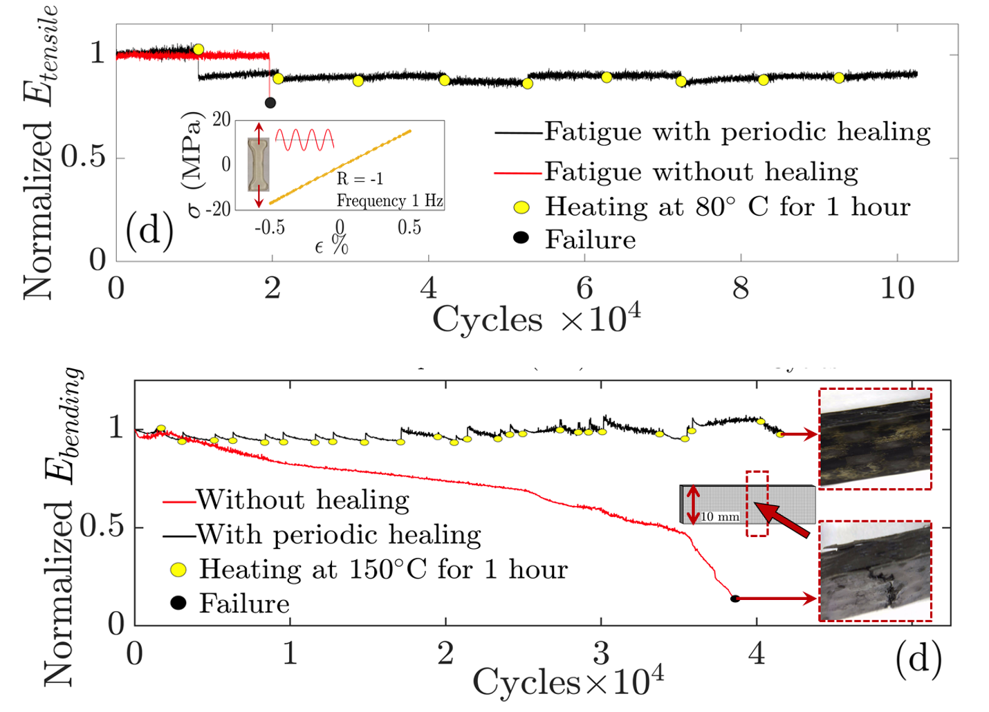
Further, carbon fiber-vitrimer composites were produced using the standard technology of carbon fiber-epoxy composites. These were loaded cyclically following a routine similar to that described above for the pure vitrimer. Figure 8 (Below) shows the variation of the stiffness during cyclic loading. The red line shows that the sample not subjected to periodic annealing accumulates damage leading to stiffness degradation, and eventually fails. The black line shows the behavior of the sample exposed periodically to elevated temperatures. In this case, the stiffness remains constant in time, which indicates that the fatigue-induced damage heals back at each annealing. Annealing extends the fatigue life of the composite beyond the range of the test.
- M. Kamble, A. Vashisth, H. Yang, S. Pranompont, R.C. Picu, D. Wang, N. Koratkar, Reversing fatigue in carbon-fiber reinforced vitrimer composites, Carbon, Vol. 187, pp. 108-114, 2022